 07 3375 6777
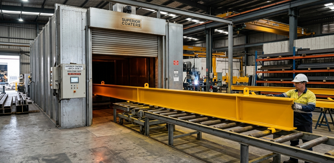
For structural engineers, commercial steel fabricators, and project managers across Australia, the pressure to deliver durable, cost-effective infrastructure has never been higher. When designing large-scale structural components—such as 10-to-14-meter portal frames, street lighting columns, transport chassis, or architectural facades—you face a critical decision during the drafting phase. How will these monolithic components be coated, protected, and transported?
Too often, engineering firms fall into what industry veterans call the “Splicing Trap.” This occurs when a component is artificially sectioned, segmented, or spliced during the design phase purely because standard, local powder coating facilities lack the capacity to process oversized elements.
While splicing solves an immediate, short-term processing limitation, it introduces a cascade of long-term liabilities: mechanical vulnerabilities, added assembly labour, increased transport complexity, and localized coating failures.
Understanding the engineering, logistical, and financial realities of the Splicing Trap reveals why designing for single-piece, continuous powder coating—leveraging ultra-large-capacity batch ovens—is rapidly becoming the standard for low-risk, high-consequence structural steel projects.
What is the Splicing Trap?
In structural steel fabrication, a splice is a joint used to connect two or more structural members. Splicing is perfectly valid when used to satisfy transport limits (such as standard semi-trailer lengths) or site access constraints.
However, the Splicing Trap refers to the practice of introducing unnecessary bolted or welded splices solely to accommodate the limited bath or oven dimensions of a coating applicator. Most standard commercial powder coaters operate with batch ovens maxing out at 6 to 8 meters. When an engineer specifies an 11-meter column or a 13-meter truss, the fabricator is frequently forced to split the member into two sections, apply the protective coating, and then reconnect them on-site.
This design compromise triggers multiple hidden engineering risks and long-term asset management expenses.
The Engineering & Mechanical Vulnerabilities of Spliced Members
From a pure structural mechanics perspective, every joint introduced into a structural system represents a potential point of discontinuity. While modern engineering software can easily calculate the required bolt configurations or weld profiles to maintain structural integrity under load, splices inherently change the behaviour of the member.
- Stress Concentrations: Bolted splice plates create localized stress concentrations around bolt holes. Under dynamic loads—such as wind forces on high-mast lighting or vibrations on transport infrastructure—these regions are highly susceptible to fatigue over time.
- The Problem of Crevice Corrosion: The primary mechanical threat introduced by splicing is crevice corrosion. When two steel plates are bolted together, a micro-gap remains between the mating surfaces. Capillary action can draw environmental moisture, salt, and airborne contaminants into this unsealed gap. Because oxygen levels inside the crevice are lower than in the open air, a localized differential aeration cell forms, accelerating steel degradation far out of sight.
The Fatal Flaw: Gaps in the Protective Barrier
Powder coating relies on electrostatic application followed by thermal curing to form a continuous, non-porous polymeric barrier over the metal substrate. This barrier shields the steel from oxygen and moisture—the two prerequisites for iron oxide (rust) formation.
When a monolithic piece is spliced, that continuous barrier is broken.
1. Fastener Damage During Assembly
When spliced components arrive on-site, ironworkers must bolt the sections together. The torque applied to heavy structural bolts frequently scores, chips, or cracks the powder coat finish immediately surrounding the bolt holes. These micro-fissures expose raw steel to the elements.
2. The Inadequacy of Site Touch-Ups
To combat assembly damage, site crews typically apply liquid touch-up paints over the scarred joint area. However, field-applied liquid paints rarely match the cross-linked density, dry film thickness (DFT), or adhesion characteristics of a factory-cured powder coat applied under controlled conditions. The joint quickly becomes the weakest link in the entire corrosion protection system.
The Hidden Logistical & Labor Costs of Splicing
Engineers and estimators often overlook the true cost of splicing by focusing solely on material weight. While a single 12-meter beam might seem identical in cost to two 6-meter beams on a spreadsheet, the fabrication and site labour tell a vastly different story.
|
Project Metric |
Spliced Design (2x 6m Sections) |
Continuous Design (1x 12m Section) |
|
Fabrication Labor |
High (Detailing, cutting, drilling splice plates, extra welding) |
Low (Straight cut, standard end-prep) |
|
Component Count |
High (2 beams, 2 plates, dozens of bolts/washers) |
Minimal (1 single beam) |
|
On-Site Rigging & Crane Time |
Doubled (Holding two pieces in place during alignment) |
Halved (Single lift directly into final position) |
|
Site Labor Hours |
High (Manual alignment, torqueing bolts, site paint touch-up) |
Low (Fast securement, no site coating required) |
|
Long-Term Maintenance |
Periodic inspection & re-coating of joints required |
Minimal (Uniform weathering across the asset) |
As shown above, eliminating the splice dramatically lowers the total cost of installation, offsetting any perceived savings from using a smaller, standard-sized coating applicator.
The Solution: Designing for Monolithic 14-Meter Batch Curing
The most effective way to evade the Splicing Trap is to partner with an industrial coater capable of processing oversized components in their entirety. Industrial facilities equipped with ultra-large-scale infrastructure change the math on structural steel design.
Partnering with a specialist coater operating an expansive batch system—such as a 14-meter batch cure oven paired with an matching inline abrasive blasting booth—allows engineers to design for single-piece continuity.
Designing for a single, continuous coating run delivers distinct advantages:
- Uniform Dry Film Thickness (DFT): A single component processed end-to-end receives a perfectly uniform application of powder, eliminating the variance in thickness and color that can occur when components are coated in separate batches or split across smaller ovens.
- Unbroken Corrosion Protection: Without splice plates or exposed fasteners, the polymeric barrier remains intact across the entire span. This is particularly vital in highly corrosive coastal environments, such as Southeast Queensland, where airborne chlorides aggressively attack coat imperfections.
- True Warranty Compliance: Major coating manufacturers like Dulux and Interpon offer structural warranties (up to 20 or 25 years for premium systems) only when the substrate preparation and coating application strictly adhere to Australian Standards (like AS/NZS 4506). Introducing site-welded or heavily modified bolted joints after factory coating can jeopardize the validity of these high-value commercial warranties.
Conclusion: Value Engineering Demands Continuous Coating
Value engineering is not about finding the cheapest individual line item; it is about minimizing the total cost of ownership while maximizing structural reliability. Designing oversized components to be sectioned down simply to fit standard commercial ovens is a compromised approach that introduces unnecessary engineering risks, inflates site labour costs, and shortens the operational lifespan of the asset.
By recognizing the limitations of the Splicing Trap early in the design phase, structural engineers and fabricators can consciously spec for massive, continuous spans. Utilizing a facility with a 14-meter batch oven capability ensures your project benefits from maximum mechanical strength, simplified site logistics, and an unbroken, warrantable protective shield built to endure Australia’s harshest environments.